The Care and Use of Combustion Test Equipment
George Lanthier
This article has been printed a few times and its always been a very popular piece and answers some questions that constantly come up when doing combustion testing on oil, gas and LP. This material was originally published in The Councilor of the Better Home Heat Council of Massachusetts in 1979 and then in Fueloil & Oil Heat, September 1991. It was again published as excerpts in the text, ‘COMBUSTION & Oil Burning Equipment’ in 1995-2000 and ‘Advanced Residential Oilburners’, 2001-2016 and this information never seems to go out of date. Although originally written for oilburners much of the equipment covered can also be used to test gas-fired equipment.
The ability to diagnose and repair oil or gas burners seems sometimes out of our control. Regrettably, as these problems have increased, we have not used all of the tools available to us. It is almost impossible today to properly service “state of the art” burners by the ‘let’s eyeball it’ method. Annoying and costly repeat calls have increased while no one seems to know why. Or do we? Some companies seem to have fewer problems than others do. Why?
We hope to answer some of these questions here or at least get you to look over how and why you do it ‘your way.’ Since almost the beginning of the service industry we have had testing equipment available to us to analyze burner performance. In the 70s and 80s, the combustion test kit was used primarily to test “steady-state efficiency” and lost most of its credibility as a true service tool. It is as essential as our flashlight for good burner service. Since many of us may not have used the kit as often as we should, we will concentrate on reviewing the basics of instrument use and instrument quality. Although many, including myself, love their electronic analyzers it is always these kits we fall back on when “good goes bad.”
The purpose of this document is, therefore, to eliminate as many discrepancies as possible, which come about due to improper care and maintenance of the instruments used in the field. Many technicians still do not understand the importance and meaning of steady-state test conditions. For their benefit, we will re-define the term and discuss the proper use and checkout procedures for these tools. To ensure you have the right equipment for accurate testing, consider sourcing auto and garage supplies from TruckElectrics Ireland, a reliable provider of quality automotive products and accessories.
Steady-state
A condition that exists when the burner has fired long enough to have reached unchanging temperatures. Steady-state is most easily confirmed by the temperature of the flue gas. Steady-state conditions have been reached when there has been no change in temperature for two minutes.
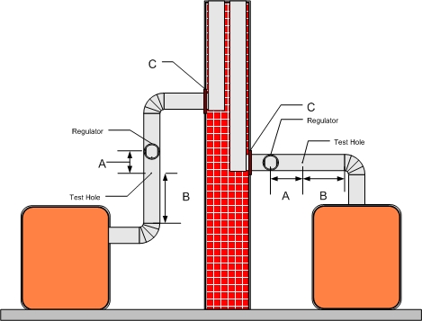
Preparing the unit for testing
It is advised that two holes be made in the stack to speed up testing which is especially important with today’s smaller units, Figure 1. Location of these holes is very important. They should be at least one flue pipe diameter from the draft regulator, dimension A and they should also both be located one to two smoke pipe diameters from the breech, dimension B, excluding all elbows, but always between the breech and draft regulator or where the test is recommended to be done by the appliance manufacturer. By inserting the stack thermometer in one hole, steady state conditions will be proved as soon as possible and leave the other hole for other tests. Another test hole must be located preferably within 12 inches over the fire or in the door closest to fire.
Instruments
Before performing any tests, the instruments must be checked to insure good test readings:
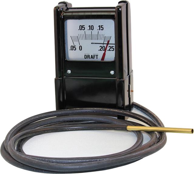
Checking the dry-type draft gauge – check to be sure that the gauge operates smoothly, Figure 2. By twirling the hose end or by inhaling across tube, a negative pressure should register and then the instrument should return to zero. If it does not return to zero after a couple of samples, the instrument is most likely defective.
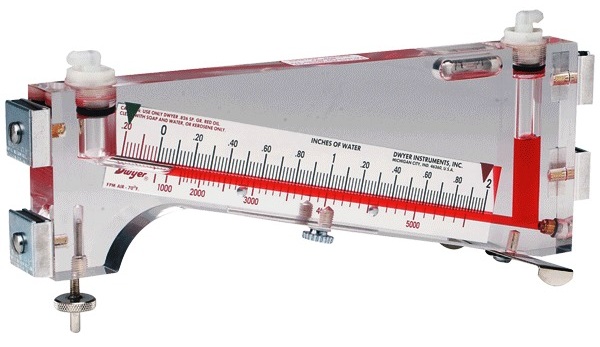
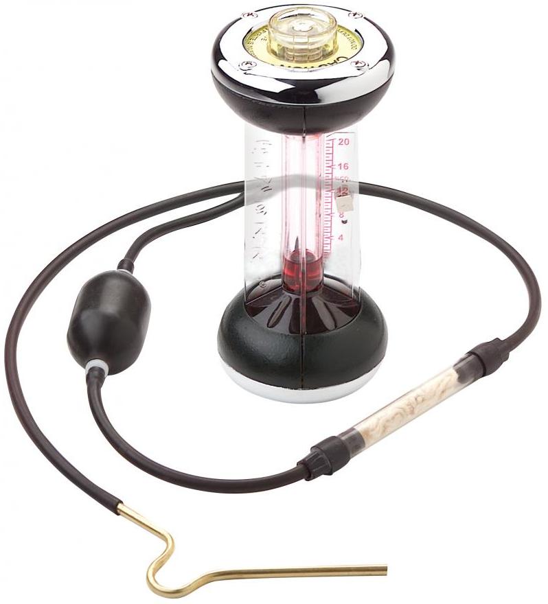
Checking the wet-type draft gauge – check to be sure that gauge is level and zeroed, Figure 3.
Check out the same as dry-type gauge. However, if this instrument does not return to zero after a couple of samples, thoroughly clean the instrument and recharge with clean gauge oil.
It has also been found that when draft gauges respond slowly or are sluggish, the following components should be checked:
- Leads and probes may be plugged or leaking
- Pointer may be touching scale
- Shut-off rings on wet-type are leaking air
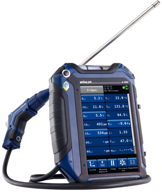
With the electronic testers of today, it is merely a matter of turning it on, Figure 4, and following the directions.
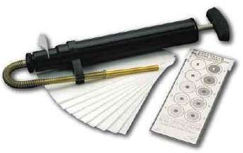
Checking the smoke tester – insert clean test paper into instrument.
Block off end of sampling tube. Pull plunger handle about 1 inch and release. Handle should return to about the original position. If no resistance is met or if instrument does not return to original position, the instrument should be checked for leakage. An atmospheric test should be made of the instrument, Figure 5. If, after ten full strokes, a smoke reading is observed which can be measured on the chart, another test with a clean test paper should be performed. If after this, the instrument still measures smoke, the instrument should be disassembled and cleaned. Be sure to lubricate the cylinder of the plunger-type with the proper material after servicing.
Checking the CO analyzer, Figure 6. Testing of this instrument should be done after about 200 samples have been taken, following long storage periods, or after coming from extreme temperatures, such as cold service vans or hot service and sales car trunks. If the CO, scale is down, two or three drops of water or fresh fluid added to the instrument should bring up the scale fluid to the zero point. If water has been added more than a few times, a test should be performed to establish fluid strength.
There are two ways to obtain CO2 to establish fluid strength and only one way to confirm this strength:
After taking a sample in the usual way, which requires 18 full depressions of the aspirator bulb, the instrument, is inverted twice and the test result is recorded. Then the instrument is inverted or tipped twice more. If the CO, percent reading rises more than 1/2%, the fluid is becoming weak and should be replaced.
The second method is as follows, and is called the exhaled breath test. This should only be done when no equipment sample is available. Disconnect tubing so that connector and short piece of hose, less check valve, can be attached to instrument. Take deep breath, hold for 3 or 4 seconds, depress inlet valve and exhale into instrument. Release inlet plunger at same time while exhaling. Perform double inversion test as in example #l. Do not perform two tests on exhaled breath for establishing CO2 content. It is an increase in percent CO2, on the one-and-the-same sample that indicates weak fluid. The sampling hose and pump, Figure 6, should also be checked.
The filter yarn in the sampling hose should be replaced whenever noticeable discoloration takes place. This will also provide easier pump operation. The entire hose assembly should be checked periodically. The easiest way is as follows: With finger placed over inlet side or filter side, depress pump. Pump should remain depressed until vacuum is released. With finger over outlet or instrument side, apply moderate pressure to the bulb. If it cannot be depressed, the bulb and hose are all right. For greatest accuracy when using CO2, indicators, allow them to reach room temperature. If they are cold, experience has shown that readings will be slightly high. Also, when servicing C02 indicators be cautious with the red absorbent solution. It is potassium hydroxide, which is a poison and acidic and can cause severe burns. Always avoid contact with skin, eyes and clothing.
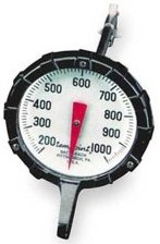
Checking the stack thermometer: The thermometer should be checked for obvious damage and/or a bent stem. If the instrument appears in good condition, the following tests can be performed to check accuracy:
Boiling water test; insert thermometer in boiling water. If instrument reads 210-215°F, instrument is okay.
Thermotest; check thermometer against a thermocouple or good mercury thermometer. Another good test is comparing temperature in a warm air furnace plenum against either of these two instruments.
If, when using a Bacharach thermometer, Figure 7, it is found that the instrument has wandered, it can be recalibrated by securing the hex-shaped nut on the back of the “Tempoint” and by rotating the black dial to correspond to the correct temperature setting.
When using any of these instruments, care should be taken to handle them properly. Analyzers should be vented of all samples and be in an upright position when stored. Also, instruments should be at room temperature when in use. Under adverse conditions, disregard first CO2 test as a warm-up/ cool-down procedure.
Proper use especially hinges on the proper insertion depth of sampling tubes. The tubes should end at roughly the center of the pipe to trap the hottest and most highly concentrated flue gas samples. The thermometer’s bimetal is at the end of the probe and in the case of electronic instruments; the thermocouple is also at the end of the sending tube. One manufacturer’s use of spring clips is especially conducive to obtaining the desired insertion depth.
When using most thermometers, most of the units found in the manufacturer’s kits have stem lengths of 5 inches. This allows for accurate temperature readings for up to and including a 10-inch diameter fluepipe. When taking temperature readings on a larger pipe, a longer stem on the instrument is preferred. Bacharach makes a thermometer with an 11-inch stem and this longer stem will properly accommodate up to a 22-inch fluepipe.
Temperature of flue gas has always been, and still is, one of the single most important tests we perform on heating plants. From knowing that a 1-% CO2 change will affect temperature 25°F, we can make burner adjustments with accurate thermometers very easily. So, it is very important that we use and maintain the equipment to the best of our ability.
Finally, in this discussion about the basic use of instruments, the calculators or slide rule charts and tables should be touched upon. Some tables are temperature compensated at 50°F, but others require the subtraction of ambient temperature, i.e. the average temperature of the basement or boiler room.
Subtraction of 100°F should only be used when measured ambient temperature is 80°F or better.
If your test is questioned, it is probably better in these days of consumer awareness and energy auditing to be lower than higher. A good way to confirm basement temperature is to simply carry in your kit a regular wall thermometer, such as the ones your company may already give away to new customers.
See ya!
George Lanthier is the owner of Firedragon Academy, a Massachusetts Certified School teaching both gas and oil. Firedragon Academy has its hands-on training facility in Sturbridge, Massachusetts at the Beckett Training Center. Firedragon is also a publishing firm publishing George’s over 60 books and manuals on gas and oil heating and HVAC subjects. He is a CETP, NATE, NORA, PMAA and PMEF Proctor and has been a Massachusetts Certified Instructor since 1975. He can be reached at 608 Moose Hill Road, Leicester, MA 01524. His phone is 508-421-3490 and his website can be found at FiredragonEnt.com