Flue Pipe Design
by George Lanthier*
This taken from our book “Advanced Residential Oilburners” and applies to powerburners both gas and oil and most other “fan-assisted” applications. The figure numbering sequence is to maintain our Copyright.
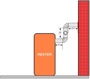
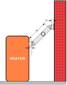
Good vents and flue pipes should be of the proper size and design. They must also be properly assembled, secured, and in pressure applications be made airtight. One of the most common mistakes made by many installers is the use of 90-degree elbows. These fittings may allow you to install flue pipes that are “squared-up” but they create so much restriction and turbulence that they actually reduce the proper flow of draft. Figure 6-1 shows an installed job using 90-degree elbows and in Figure 6-2 is the same job using 45-degree elbows. Although Figure 6-1 may look better to you, Figure 6-2 will have better draft qualities, vent better and have less pressure drop for the burner and chimney to overcome. The next time you are asked to replace the flue pipe on a poor draft job that has rotted out, try this method. I think you may be quite surprised.
The flue pipe should always be properly secured by using rivets or drill screws. The use of drill screws allows for the removal of the pipe for cleaning and for the replacement of defective sections. After securing a run of flue pipe, the pipe should be properly supported using the correct non-combustible materials and secured at both the breeching and smoke hood of the unit and at the vent, chimney or stack. In pressure-fired applications, whether they be positive pressured such as forced draft or negative pressured such as induced draft, all flue pipes should be sealed with a proper sealing material like a high temperature silicone. This will not only eliminate draft changes within the flue ways but will also help to prevent complaints from soot, smoke and odors.
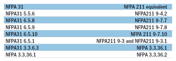
It turns out that flue pipe design is not as easy as some people think it is. In fact, when it comes to the codes and good industry practice, many trades people are doing it wrong. The codes are very specific in regards to oilburners and remember that although your state may have its own code, the manual that came with the appliance probably says that you must also be in compliance with NFPA31, and when it comes to venting you must be in compliance with NFPA211. And then there’s what works. We’re going to start with NFPA31 and end up with NFPA211. There are three excerpts from NFPA31-2001 that we need to look at and they are:
- 3.3.6.3 Mechanical Draft-Type Burner. A burner that includes a power-driven fan, blower, or other mechanism as the primary means of supplying air for combustion.
- 3.3.6.4 Natural Draft-Type Burner. A burner that depends primarily on the natural draft created in the chimney or venting system to induce the air required for combustion into the burner.
And then we have this other point to note:
- 6.5.1 An oil-burning appliance shall be placed so that the chimney connector is as short as practicable. For natural-draft appliances, the horizontal length of a chimney connector shall not exceed 10 feet. (3m) unless a draft fan is used. For appliances requiring a negative chimney draft, the chimney connector shall not be longer than 75% of the portion of the chimney above the chimney connector inlet.
We don’t use natural draft burners anymore, they are the old pot and sleeve type burners and many younger techs have no idea what I’m talking about and that’s okay! Everything we use today is a mechanical draft burner and has a fan in it; Beckett, Carlin, Riello, Wayne, etc. So you can throw NFPA31 3.3.6.4 and the draft inducer out the window for this discussion. But, we have to take a good look at that 75% thing.
Essentially I hate the term smokepipe. I’ve been doing my part to educate the industry to use the term flue pipe in front of retail customers since 1975. Why even paint a mental picture that oilheat is dirty in any way? Keep in mind that in the codes and standards they don’t refer to them as either flue pipes or smokepipes, but rather as a “chimney connector”. Some of the other filthy street words that burnermen use are “blast tube” and “jet line” instead of air tube and nozzle line. I guess if you’ve never had a complaint about a noisy powerburner, then it doesn’t matter.
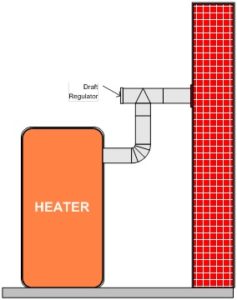
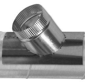
Another thing that really angers me are right angled 90-degree turns on flue pipe runs. The most dreaded tee that can be used with any powerburner is known in the field as a “plumber’s tee”. It is acceptable on atmospheric gasburners, but not on appliances using a powerburner. Figure 6-3 shows the use of a plumber’s tee and when you go through most manuals you’ll see that although it’s correct for atmospheric gas, it’s never been recommended for oil. In fact, it’s even wrong on many gas jobs today. The trick again is whether the burner is mechanical draft or natural draft. With natural draft, like atmospheric gas, it’s right. With any powerburner, it’s wrong. It has to do with Bernoulli’s Principle and venturis and Y or jet tees also known as mono-flo tees found on hydronic systems.
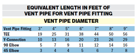
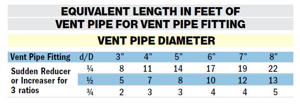
An explanation of TEPL is required before we continue. TEPL is the Total Equivalent Pipe Length of a flue pipe. Table 6-1 is a brand new one that comes from Field Controls. It does a great job of explaining how to calculate TEPL for the fittings used.
Let’s work a couple of examples. First of all, the traditional way. In Figure 6-1 is a drawing which shows a simple install of an oil-fired appliance and we’ll set the flue pipe diameter at 6 inches.
We have three pieces that are 18 inches, 24 inches and 23 inches in length that total 65 inches or about 5½ feet, and then we add in for the two 90 degree elbows at 11 feet each for a grand total of 27½ feet of TEPL. In Figure 6-2, I have used two 45 degree elbows at 5 feet each and added them to the flue pipe run of 7 inches, 5 inches and 48 inches that total 60 inches or 5 feet giving me a grand total of 15 feet of TEPL or roughly half of doing it the conventional way. Now comes the best part, the tee.
The bad news for those of you who love that plumber’s tee, Figure 6-3, is that the dimensions are the same as Figure 6-1, but we remove one elbow and add the tee’s TEPL from the chart.
We now have pieces that are 18 inches, 24 inches and 23 inches in length that total 65 inches or about 5½ feet, and then we add in for one 90-degree elbow at 11 feet and a tee at 38 feet for a grand total of 54½ feet of TEPL. Guess what? You may be in big trouble now. Remember that thing about ‘the chimney connector shall not be longer than 75% of the portion of the chimney above the chimney connector inlet?’ Well, let’s see what happens with an atypical New England chimney of about 35 feet high.
With a 35-foot chimney we’re going to deduct 5 feet for the height of where the flue pipe goes into the chimney, leaving us an actual chimney height of 30 feet. Some 75% of that leaves us a working dimension for a flue pipe of no more than 22-½ feet. So let’s look at the flue pipe design.
Using the conventional way and using 90 degree elbows we ended up with a TEPL of 27½ feet, or 5 feet more than what is allowed by the codes. Using a plumber’s tee and one 90 degree elbow we ended up with a whopping 54½ feet of TEPL or almost two and one-half times the allowed flue pipe size by code. Finally, there’s the right way as far as the codes are concerned.
By using the 45 degree elbows I ended up with 15 feet of TEPL or about 65% of the code. (By the way, are you finally starting to realize that you really didn’t know what you thought you did about powerburners, why it’s the title of this book and why you really need to take our seminars. Let me tell you, even we don’t cover it all. Okay, that takes care of NFPA31 for now on this subject except for a few other things I need to review.
6.5.6 states essentially that you can’t have a flue pipe smaller than the appliance outlet.
6.5.8 states that you must pitch it at least ¼ of inch per foot of run.
6.5.9 says watch the turns and keep the elbows to a minimum and of course;
6.5.10 says that you must properly support it and fasten all of the joints.
That’s the really short version, and I truly suggest that you buy a copy. You can get NFPA31 at www.nfpa.org and for those of you in MA you can get our book The MA CODE Guide from us only by attending one of our Code seminars.
NFPA211 is all about chimneys and as it turns out is used in all states that have adopted NFPA1. I honestly believe that every oil company service department should have a copy of this, and every service technician and installer should be made to read it. All of my quotes are from the 2000 Edition, but they’re mirrored in the 2003 Edition and the 2006 Edition. Let’s first of all go over the duplicates that are carried over from NFPA31 to NFPA211 in Table 6-2.
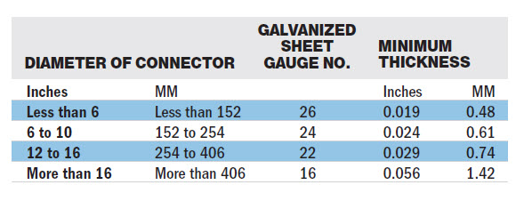
Last but not least is my favorite. The problem is that this is one of those things in NFPA211 that even gets a lot of the good guys on a smoke, soot or fire insurance claim, Table 9.2.2.3, Metal Thickness for Galvanized Steel Pipe Connectors as shown in the Table 6-3. This may come as a shock to many of you, but as you can see even the gauge of the flue pipe is called out. It’s one of the things insurance investigators go for when they don’t want to pay the claim and can’t find anything else to go to subrogation with. The trick is, don’t let them. Do it right, every time. Some of you may also think this is new; forget that excuse, this goes back to the 1970s. Don’t let wholesalers sell you their mistakes either. It is not okay to use what’s available, if it’s wrong, it’s wrong. Keeping in mind that we are still following the NFPA Standards, NFPA31 and 211, for this subject NFPA and I can’t stress enough that ANY manufacturer’s requirement supersedes anything either of us have to say. No surprise there, any code regulator or instructor always gives the manufacturer of a listed, certified or accredited product more value than the code. Nobody knows the product better than the manufacturer, FACT!
We’re now going to look at two examples using tees and 90-degree elbows to make it bad, and Y-Connectors and 45-degree elbows to make it as Goldilocks always says “just right”. We’re also going to keep the parameters the same. The chimney is still 35 feet high and the flue pipe on the heating unit is 6 inch, but now it’s a furnace and to that we’re going to add a water heater with a 5-inch flue, sound familiar?
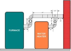
Let’s first do it the traditional way. In Figure 6-4 we have a drawing which shows a simple installation of the oil-fired furnace and the water heater. We have 6 pieces that lead from the furnace to the chimney. The lengths are 11 inches, 13 inches, 12.5 inches, 14 inch and two 24 inch pieces that total 88.5 inches or about 7½ feet, and then we add two 90-degree elbows at 11 feet each and a tee at 38 feet for a grand total of 67½ feet of TEPL, amazing. I’m not even going to worry about the water heater in the winter, but in the summer it will have to overcome 50½ feet of TEPL just by itself.
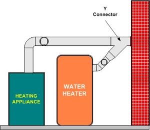
In Figure 6-5, I’m using 45-degree elbows again and this time I’ve used a Y-Connector, Figure 6-6 to make the changes. From the furnace I now have a run of 4 inches, 24 inches, 7 inches, 24 inches and 21.5 inches for 80.5 inches or about 6¾ feet of run. Add 20 feet for the Y and you end up with a grand total of 26¾ feet of TEPL or roughly 1/3 of doing it the conventional way. Again, if I just look at the water heater, the burner will only have to overcome about 17½ feet of TEPL or about 1/3 of the other method. But what about that transition, does that count? Oh sure. Again a great chart from Field Controls can be found in their literature. This time there’s a tricky part unless it’s only one pipe size, then you use the ¾ d/D dimension. The reducer or increaser ratio (d/D) small diameter divided reducer ratio is d/D = 4/8 = ½. To estimate the equivalent foot length for the fitting, use the smaller pipe diameter for the equivalent length figure.
Example: 4 inch to 8-inch reducer; the reducer ratio is ½ and the smaller pipe diameter is 4 inches. So, from the chart the equivalent would be 7 inches.
For our job that means adding 3 feet to the 17½ feet bringing the total TEPL for the water heater to 20½ feet, again well below the chimney design of 22½ feet we have already established for the chimney. We said that we had a 35-foot chimney. We deducted 5 feet for the height of where the flue pipe goes into the chimney leaving us an actual chimney height of 30 feet. Seventy-five percent of that leaves us a working dimension for a flue pipe of no more than 22½ feet which is the maximum allowed by both of our NFPA Standards.
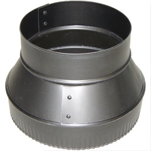
For any other application you should follow this procedure as outlined by Field Controls in Table 6-4 using a cone or tapered transition piece as shown in Figure 6-7.
Okay, that’s all out of the way. Now I want to take you through how I would do a multiple unit. I don’t go against OEM specifications on a new installation, ever! But, when a job is a few years old and it has been a problem since day one, it’s time to try something else. Numbers and good simple math just don’t lie.
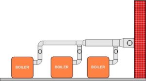
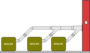
Both of these jobs have 7-inch flue pipe coming out of the breeching of the boilers and we’ll do the sizing of the combination flues later. In Figure 6-8 we have another one of those jobs loaded with 90-degree elbows, four to be precise. In Figure 6-9 we have the same job converted to 45-degree elbows. The tees have become Y-Connectors and I just want to focus on those since the pipe lengths and transitions will be just about the same and you know how to figure those now, right? The four 90-degree elbows equal 12 feet each and the two tees are worth 44 feet each for a total of 136 feet of TEPL, and remember that doesn’t include the transitions and piping. But, if I switch to four 45-degree elbows at 6 feet each and add the two Y-Connectors at 23 feet each, my new TEPL just for fittings is now 70 feet of TEPL or roughly half of what I began with. By the way, just to vent that 90-degree job without the piping figured in you need a chimney 180 feet high, think about it!
At this point it’s time to do some sizing of multiple unit flue pipes and wrap this section up. We have so far sized everything but the common vent pipes and taken a look at transitions. What about those transitions, and again there’s a right way and a wrong way.
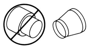
In Figure 6-10, courtesy of the fine folks at Tjernlund Products, you can see that there are two types of transitions. The one on the left is wrong and is known as a pancake reducer. The one on the right is correct and is known as a cone or tapered type of reducer as we already showed you in Figure 6-7. Naturally both have the ability to transition up or down and so could also be called increasers. The cone type is the only one we’ve shown because it’s the right one for flue pipes. I don’t know where you would use a pancake type, but I would never put one in a flue pipe and I know they make warm air ductwork whistle. The cone type allows the fluegas to easily transition from one size to the next without any additional turbulence added to the fluegas. The pancake reducer will create a lot of problems and can even increase the pressure drop in the flue and create a partial blockage by creating a bullhead tee effect. Let’s say that instead of using the cone type we use a pancake type and we are decreasing pipe size with the flow headed into the fitting from large to small. The air (fluegas) will strike the sides of the fitting and curl back onto the air trying to get out and a pressure fight begins. This pressure fight will increase your pressure drop and lower your draft flow and there goes the ball game, just like in a bullhead tee.
Here’s the table I use for building common vents, Table 6-5, and although I don’t remember where I found it, it has never let me down.
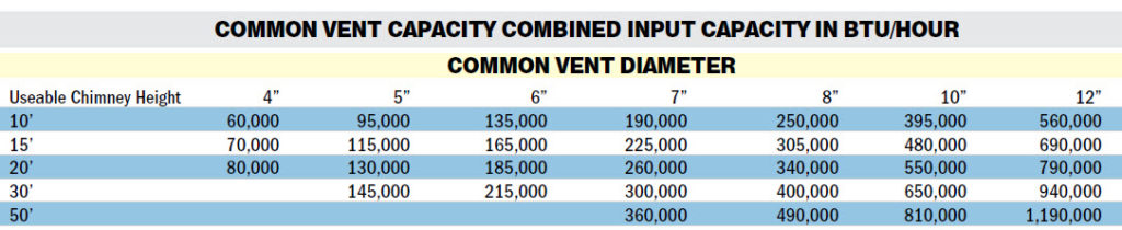
Keep a few things in mind when using this chart. First, it is not meant to replace any OEM’s specifications and should never be used in place of an engineered system. Second, the useable height is from where the common vent enters the chimney to the top and that the chimney size is equal to or larger than the largest size of vent used. If the chimney is too big, the best bet is to reduce it down with a liner or expect condensation stains and debris normally called ‘pigeon droppings’ to turn into seagull size.
Let’s work an example using Figure 6-9. Each one of these three units has an input capacity of 1.50 gph of fueloil or 208,500 Btus per hour using 139,000 Btu/gallon fueloil. Each unit has a 7-inch flue so from the furthest unit on the left the flue remains at 7 inch until we meet the second unit. At this point, the Y-connector, the flue pipe becomes 10 feet based on our 22½ foot useable chimney height and the input now 417,000 Btus. As we pick up the third boiler, the input becomes 625,500 Btus and our common vent from the second Y-connector into the chimney is now 12 feet based on the table.
Two things to watch. Did you notice that I used the 20-foot line instead of the 30-foot line? Always work to the worse condition. That’s why I also picked a Btu range that was greater than what I had. Although I have fans in my burners, I size as though I just had the chimney, pipe and fittings to work with, because when worse comes to worse, that’s about it.
In multiple or modular applications, a draft control must be installed in the flue pipe of each unit and in the common breeching, Figure 6-8 and Figure 6-9 due to a higher production of thermal draft.
Through the use of multiple draft controls, a very high negative draft can be gradually reduced down to a more manageable rate at the appliance. Don’t be afraid to use several draft controls, they are still cheaper than fuel and unnecessary repeat service calls.
Okay, that’s it except for one final thing and this goes back to Mr. Floyd Olmstead and the Handbook of Domestic Oil Burning. Mr. Olmstead probably knew more about draft than anyone I’ve ever met or read and he is the written voice of the past that has led me on a quest to make oilburners work without problems. In our books, both Mr. Olmstead and I have a chart that proves without a shadow of a doubt a bit of common sense and engineering. That little fact is something that many take for granted or just don’t know about, and is the key to why today’s equipment just doesn’t work the way it used to. Know what it is? Do you know why flue pipe design is so critical? Because quite simply, when you cut your stack temperature in half, you cut your thermal draft capability in half, and that’s the rub.
Unless you plan to put a lot of expensive fans all over the place and push and pull those flue gases outside, you better learn Mr. Olmstead’s theories, follow the codes and standards and make sure you also have a balanced draft with as much air coming in as you have going out, or as I call it, “inlet draft”. Much of the material on flue pipe design was published as magazine articles in a couple of different magazines and is constantly used in my teachings and the question comes up all of the time, “why hasn’t anyone talked about this before?” Well, actually it has and has been since day one.
Each manufacturer tells us how to construct a flue pipe to their specifications and to follow the guidelines of UL, NFPA and local codes and in addition how to construct the flue ways all the way to the top of the chimney. However, with the addition of powerventers, flue pipe design is much more specific as to construction. As a teacher and consultant I found that not as much time or words had been paid to the venting of oil as had been devoted to gas. In researching this and noting that in fact many draft problems that have been with us for years were increasing, the only thing left to explore and document was a better way to design oil-fired appliance flues. Many have used the recommendations we just covered since I first started teaching them many years ago, and I’m sure that if you use them you will find many of your draft problems will be diminished or disappear.
See ya.
*George Lanthier is the owner of Firedragon Academy, a 25-year-old Massachusetts Certified School teaching both gas and oil and other heating subjects. Firedragon Academy has its hands-on training facility in Sturbridge, Massachusetts at the Beckett Training Center. Firedragon is also a publishing firm publishing George’s over 60 books and manuals on HVAC subjects. He is a CETP, NATE, NORA, PMAA and PMEF Proctor and has been a Massachusetts Certified Instructor since 1975. He can be reached at 608 Moose Hill Road, Leicester, MA 01524. His phone is 508-421-3490 and his website can be found at FiredragonEnt.com