Nearsighted-Revisited: Cad Conundrum
By George Lanthier
Back in 2012 I did an article called “Nearsighted?” and in it spoke on cad-cell location, sighting and troubleshooting. If you read that article and have my books, or attended one of my seminars, you know that to me the living and breathing greatest example of a “burnerman” is the imbecile who paints the inside of burner air tubes silver or white. This guy not only doesn’t have a clue of what he’s doing, but he’s also a full blown menace to our society, real technicians and the future of oilheat—in addition to just being a flat-out lazy hack. You don’t want to be one of these guys in a legal situation because you wouldn’t believe how many soot and smoke damage cases are caused by this turning out to be the “most probable cause.” Even if somehow you could try to justify it as soon as they start opening those air tube boxes in court “you’re done, stick a fork in it.” Think about the burners you work on every day—the majority of the tubes are black or not painted inside at all, right? Well, when that comes out in court, as they say, “you just lost the case,” and trust me it’s not a coincidence that they are mostly all painted black.
I recently got involved in a debate on one of the many Facebook groups I belong too. This particular one is just for teachers apprentices and boy-oh-boy do the “greenies” have some great stories about the “old pros” and of course painting tubes and “shortcuts” came up. It was nice to see the teachers and senior guys who inhabit that page really raise hell when a kid asked “are the paint jobs okay?” Wow, did he get a lesson but he asked the greatest question of all, “Just how do you fix it then?” Many guys quoted my books and articles (very humbling) and then the rookies again asked “how?” Well, here it is one more time, and from a different point of view with some brand new pictures.
It’s still my opinion that the first and best option is to relocate the cell and it is also this location that can act as the position for performing a “sighting test” using “The Lanthier Scale” for initial burner adjustments. We have talked about this before and how to use a standard cell for setting up any burner including a Riello “by eye,” and you can read any of my articles at www.fueloilnews.com.
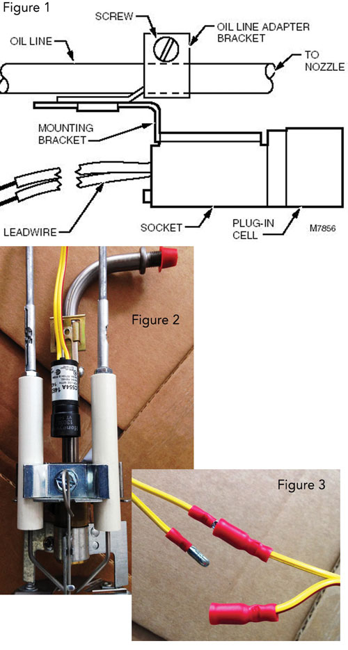
In Figure 1, provided by Honeywell, we see the cad cell repositioned onto the interior oil line. In Figure 2 we show it in reality on a Beckett “M Head” drawer assembly. The bracket, mount and hardware are supplied with the Honeywell Super Tradeline Cad Cell Package C554A1463. This is a tried and true solution and when cad cells were first introduced the way many of us brought the technology to older burners. The “tube bracket” has also been used by many technicians to ensure an adequate signal reaches the control. Many burnermen do not like this solution however, since it can make the drawer assembly harder to service, but technicians know that’s what they make crimp-on connectors for. In my last article we showed a two-pole crimp-on connector that is used around many oilburner devices including nozzle heater connections. In Figure 3 is another way to do it using “bullet-type” crimp terminals that for many are much easier to find and work with. By using that Honeywell kit however it’s not voodoo, it’s “an accepted industry practice” and that’s a big difference in court.
As history tells us, the cad cell has been a reliable, inexpensive method for flame detection for the oil industry for almost 60 years, and as technicians we must be prepared to make the burners we work on everyday work as well as possible. But, more importantly, it’s essential that we use methods that are safe and always follow the golden rules of “good industry practice.”
Finally, we will be teaching the new MA Oilburner Code the hybrid 527CMR4.00/NFPA31 beginning in early 2015, so keep an eye on our ads with dates and locations early next year.
See ya.
*George Lanthier is the owner of Firedragon Academy, a Massachusetts Certified School teaching oil, gas and general heating topics including management and system design. He is the author of over 60 books and manuals on gas and oil heating and HVAC subjects. He is a CETP, NATE, NORA, PMAA and PMEF Proctor and a Massachusetts Certified Instructor. He can be reached at 608 Moose Hill Road, Leicester, MA 01524. His phone is 508-421-3490 and his website can be found at www.FiredragonEnt.com
I am a former oil burner tech and noticed your article. I ‘ve been in the computer/electronics died for many years amd am familiar with the connectors shown in Figure 3.
I’m curious about rhea performance of these connectors in an environment that includes vibration, heat and dirt.
We use similarly designed connectors in test equipment where we have experienced connectivity problems at times due to wear, and vibration.
I was a young apprentice when we upgraded from the old Honeywell RA117A and other variations. I remember retrofitting some burners. Old She’ll head burners could be a real challenge , which is where attaching to the gun assembly was first tried in our business. That was 1969-70 ish. Lots has happened since then.
I got a kick out of anyone thinking to paint the inside of the blast tube though!
I’m not 100% sure on this but I seem to remember using a little in-line analog VOM to measure the current flow to the relay which allowed us to peak the sensitivity of the cad-cell.